This week, we will be building a kinetic sculpture. I have long been interested in the concept of Strandbeest. It’s a creation of a Dutch artist, Theo Jansen, who began building large kinetic structures from PCV pipes in the 1990s. Strandbeest translates to “beach monster” since many of his sculptures are left on Dutch beaches to roam freely. They are mainly wind-powered; however, some more elaborate designs use pressure in their pipes to move.
I will be building a very simple Strandbeest. Since the design is quite challenging and costly, I will make just one pair of legs. I have very limited experience in mechanical design, so I tried to find a reference for a 3D Printed Strandbeest. One excellent video is from Engineezy, showing multiple designs of the mechanism. Additionally, I have referenced This video as well, although most of the inspiration came from the one above.
The mechanism behind the Strandbeest leg was invented by Theo Jansen in the 90s. An algorithm running on an Atari computer was used to solve for the foot’s path using various leg dimensions. Consequently, he has found proportions that work quite well, which were referenced in our design.
I have used Fusion360 to create the model. The link proportions were copied from Wikipedia to create the mechanism. However, making the linkages directly would result in overlap due to their width. This means we need to layer the leg to avoid collision. Below, you can see the layered approach. This layout was taken from the Engineezy video mentioned above.
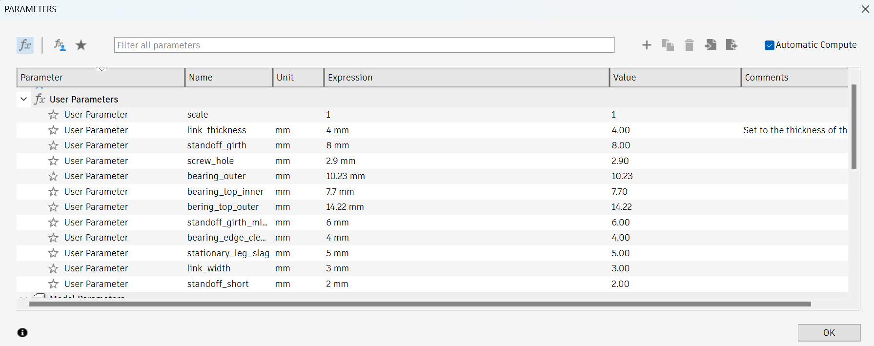
The next challenge was the joints themselves. I wanted to use a bearing to minimize friction in the mechanism. There were a few key things that I’ve learned. Proposed in This video, I have used the following formula: \( d_{\text{CAD}} = d_{\text{bearing}} + d_{\text{nozzle}}\cdot0.55\). Where \( d_{\text{CAD}}\) is the hole diameter used in the CAD drawing, \( d_{\text{bearing}}\) is the diameter of the bearing specified by the manufacturer, and \( d_{\text{nozzle}}\) is the printer nozzle diameter, in my case 0.4mm.

Unfortunately, there was a slight problem. Since I was printing almost all the parts at once, the links at the edge of the print bed slightly warped due to uneven surface temperatures. This has resulted in the shrinking of the bearing holes, thus making the bearings difficult to assemble. I could not press fit them, since the shrinkage was too large. Consequently, I had to use a cutter tool to remove the excess plastic around the rim of the linkage and make the dimensions right. This problem disappeared when I printed the parts in smaller badges. The holes in this case were slightly wider, so the bearings did not hold without superglue. Another observation is that even those bearings, that could be press-fitted fell apart later. This has led me to glue all the bearings in place.
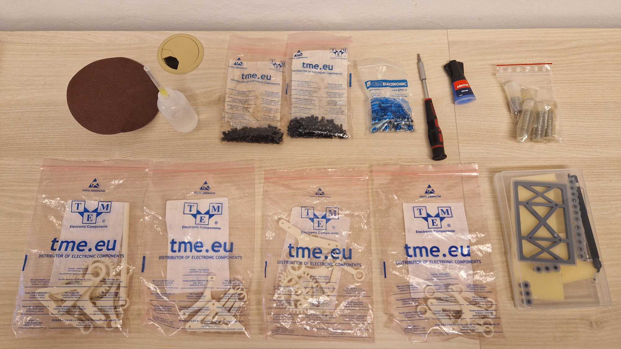
I have bought 40 pieces of the 623 (CN) 3x10x4 mm bearing \(d_{\text{inner}}\) x \(d_{\text{outer}}\) x \(\text{height}\) and 5 pieces of the MR 148 ZZ (CN) 8x14x4 mm. The total price for the bearings was 39.16 euros, which came as a bit of a surprise to me, but not in a good way :))

Another interesting design choice is the gears. Since I have 3D printed spur gears before, I have had the experience of gear disengagement during operation. Trying to solve this issue, I have opted for a Herringbone gear design. Since the gears self-align, they seemed ideal for this type of application. The design was done using a GF Gear Generator plugin in Fusion360. I was surprised at how well the locking of the gears worked. On the other hand, this very same effect has caused friction in the gears due to imperfect printing. I believe using SLA could mitigate this effect, however, even with FDM, the design was functional.

The mechanism was made to work with three pairs of legs all offset by 120 degrees. You could see tiny marks on the smaller gear marking the 120-degree shift. This was a mistake and the marks should have been on the larger gear. Since I have just two pairs of legs, I have found the optimal phase shift is 180 degrees, although the motion is not as smooth as it would have been with three pairs.
The assembly itself took multiple hours. Huge thanks go to Vít Brázda for helping me with his 3D printer, as I would not have made it in the deadline just with mine. I have decided to 3D print tiny rubber feet from flexible filament for the Strandbeest to increase friction of the legs. I was surprised to see a noticeable increase in the feet’s grip. Below are some photos of the results: