Scannning & 3D Printing
Week 3
The Idea
This week, we are learning about 3D scanning. For some years now, I have had my eyes on photogrammetry for a very specific reason. I own a small collection of Soviet-era vacuum tubes. When searching images on Google, some of the more special tubes are very hard to come by. I have wanted to make a 3D library as some form of a modern archive. This is a perfect opportunity to get my foot in the door for the first time and see how difficult it would be.
Scanning Basics
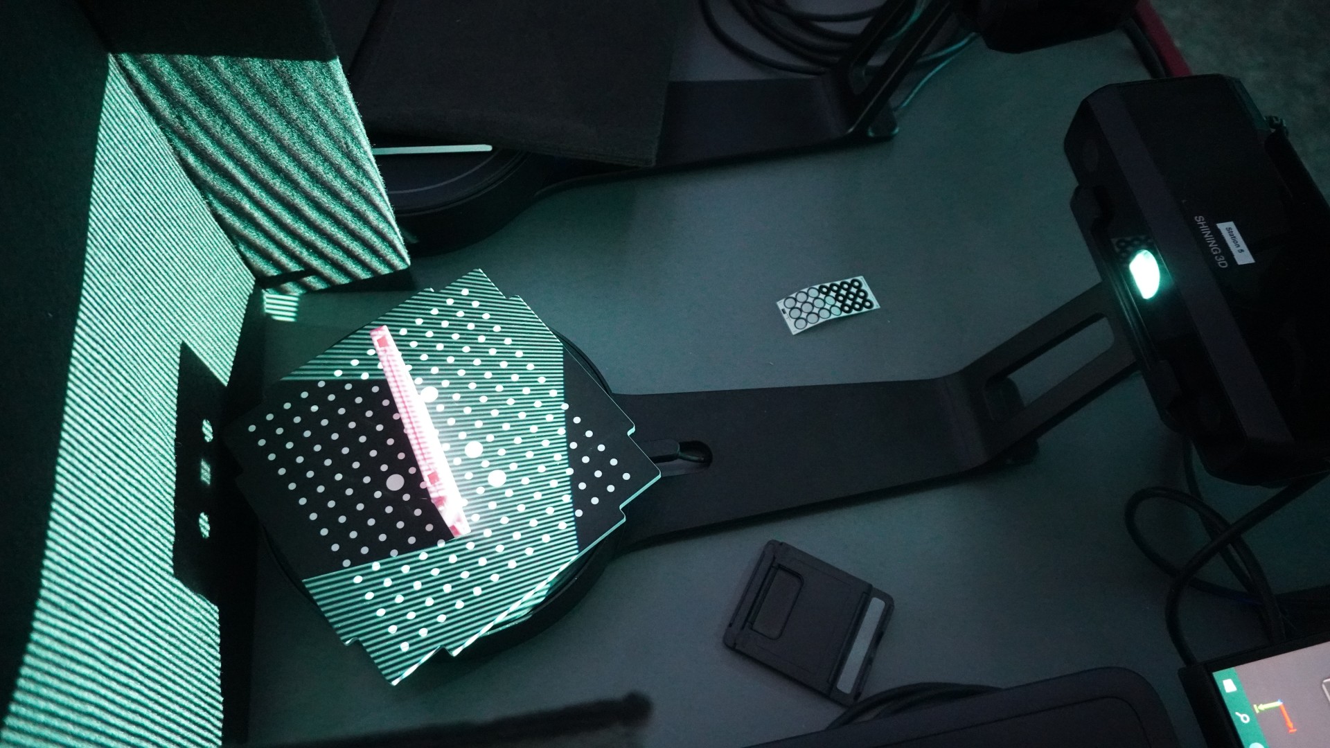
First, we need to become familiar with the EinScan-SE desktop scanner from Shining 3D. It can be used in two ways, with or without a turntable. Since we had it set up with the turntable, our scanning area was 200x200x200mm. This will become a slight problem later down the line. To increase precision, we put a board with tracking markers on the truntable surface.
I wanted to scan something simple at first. A cassette has a relatively simple shape, so it will be our first target. I set the first scan to have the minimum number of images (just 8) and to be without a texture. I will not be including the scan here, as it was just for testing purposes.
Final 3D scan of the casette
After the first scan showed the need to recalibrate the machine, I could finally proceed to capture the model with texture. I set the machine to take 12 images per scan, and in total, I made three sets of them. Each time, I rotated the cassette to a different side to help increase resolution in that area. The final scan can be seen below. Please note that the number of vertices was deprecated to fall inside the Sketchfab upload limits.
 The scanner uses structured light to help capture the surface
More Difficult Objects
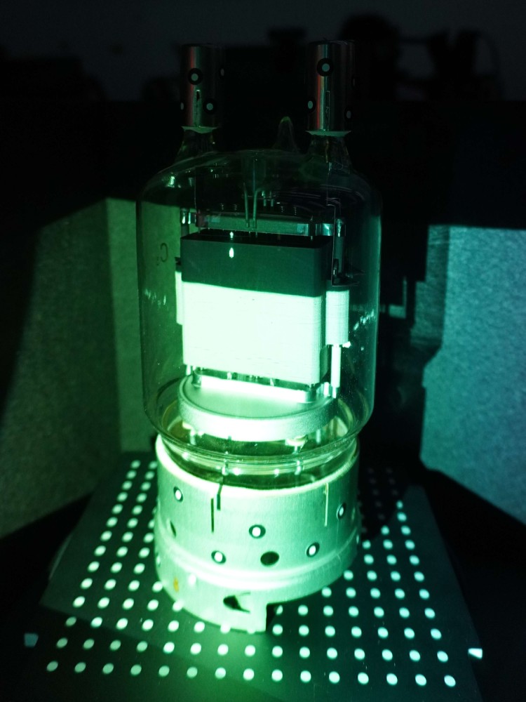
As the second object, we will try scanning a vacuum tube. As a fun fact, the tube we are working with is the infamous ГУ-81М (GU-81M) generating pentode from the Soviet Union. This happens to be one of the most well-known high-power vacuum tubes among hobbyists.
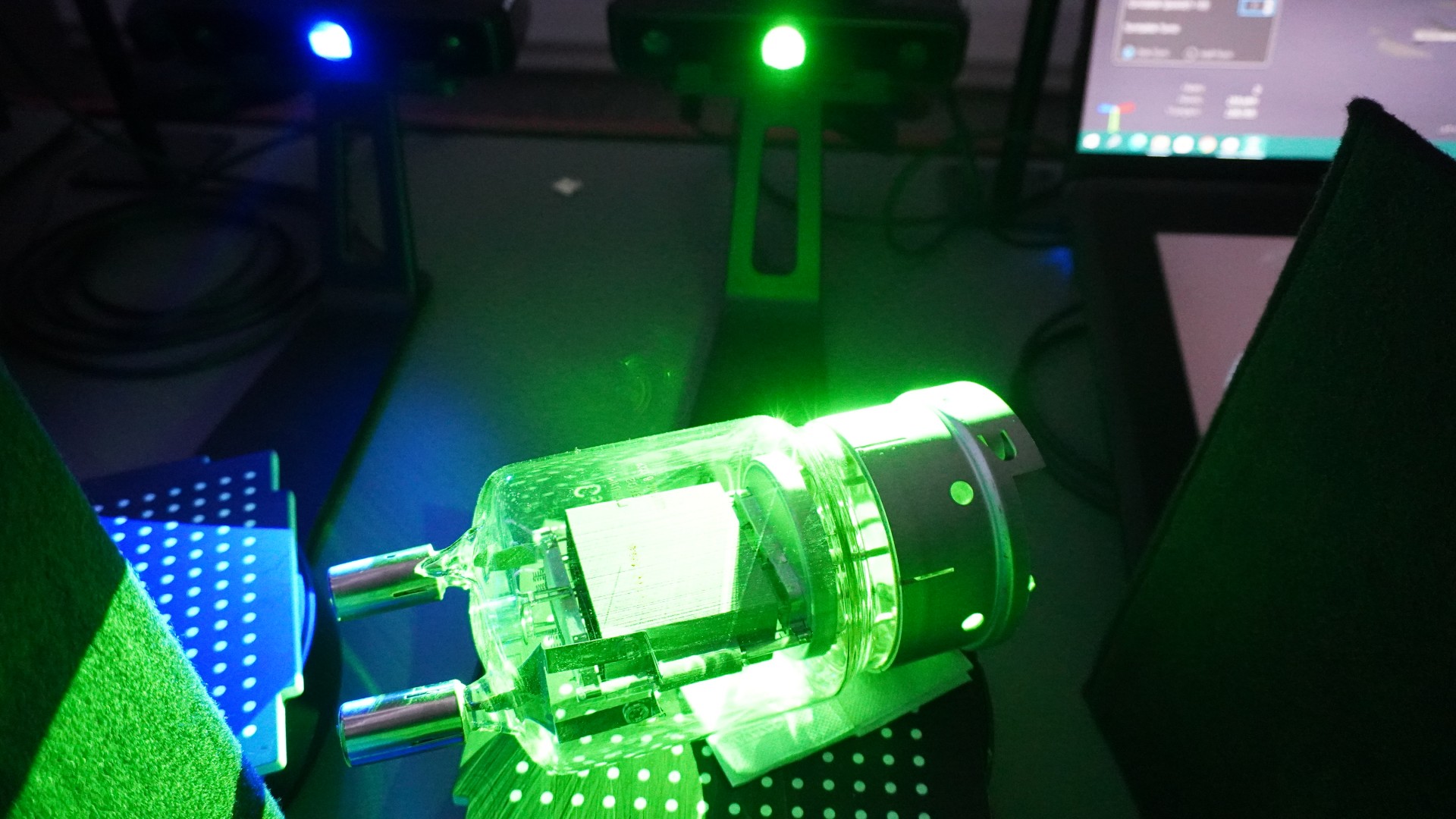
After placing it onto the scanning surface, I quickly realized the scanner was too small to fit the entire tube. To account for this, I placed it on a side and ran a few more scans hoping it would capture the entire model. To some degree it was successful, however, the metal surfaces of the tube made it a bit more difficult to get a proper scan. Furthermore, since the outer shell is made from glass, the scanner had a hard time capturing the internal geometry. I was surprised to see the glass did not get captured whatsoever.
 The light reaches only the bottom half
 Texture mapping for the green channel. The scanner shines red, green and blue light to measure the intensity of each color channel reproducing the texture.
 Tracking markers on the tube
To help with the reflectivity issue, I used tracking markers all over the tube. After running a new scan with the markers on, I could not see any difference in the quality. Quite the contrary, since I was doing a texture scan, the markers interfered with the original texture captured by earlier scans.
The final model was a mesh of point clouds in the Shining 3D software. Since the scanner could not capture the entire object properly, the software couldn’t reconstruct the image into a .obj file. This was a bit disappointing and I believe photogrammetry would yield better results.
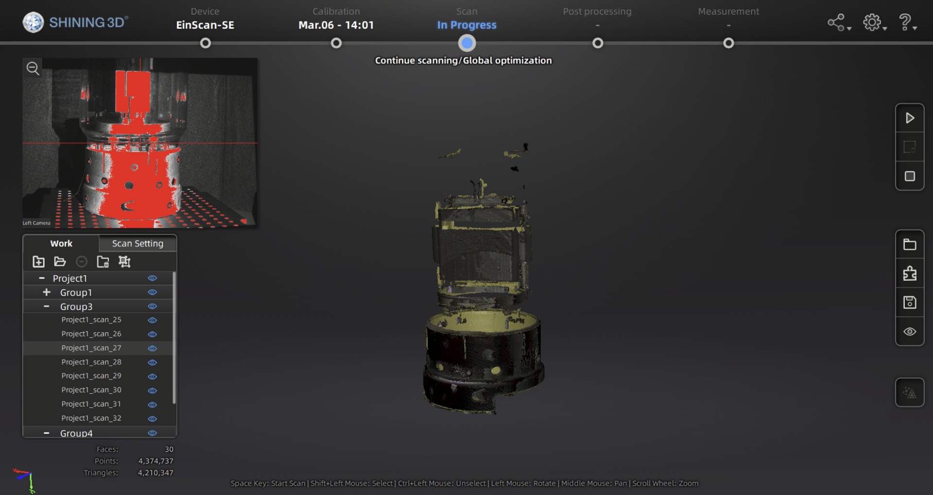 Final mesh in the Shining 3D software
3D Printing
The second task for this week was 3D printing. As I am designing a laser as my final project, I have decided to invest time in CFD (Computer Fluid Dynamics) simulations to verify the correct design of the heatsink. Much of the time was spent in Fusion360 modeling and simulating the thermal performance.
I ran six studies changing the fin count, fin height and heatsink base parameters. I have managed to bring down the simulated temperature from 191°C to 83°C.
 Render of the heatsink in Fusion360
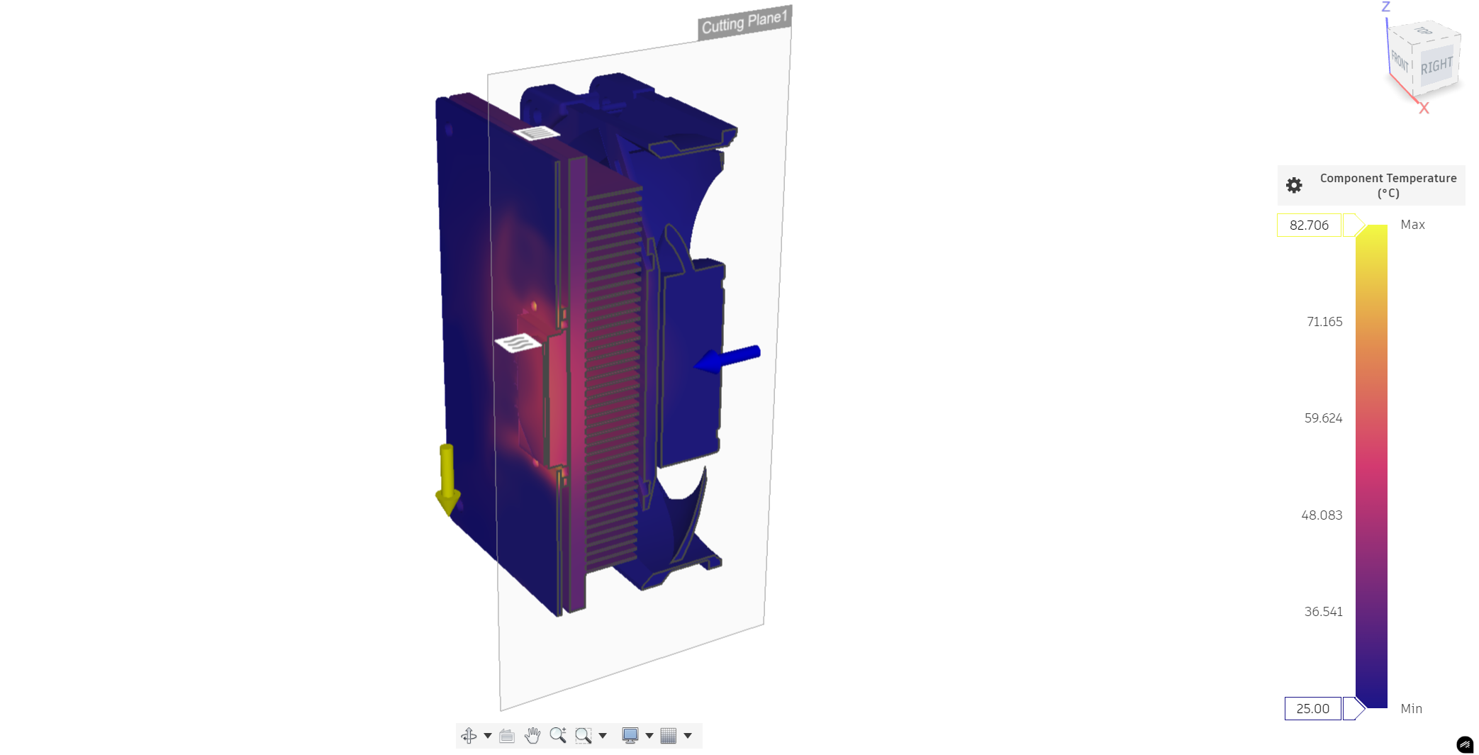 Thermal simulation of the heatsink
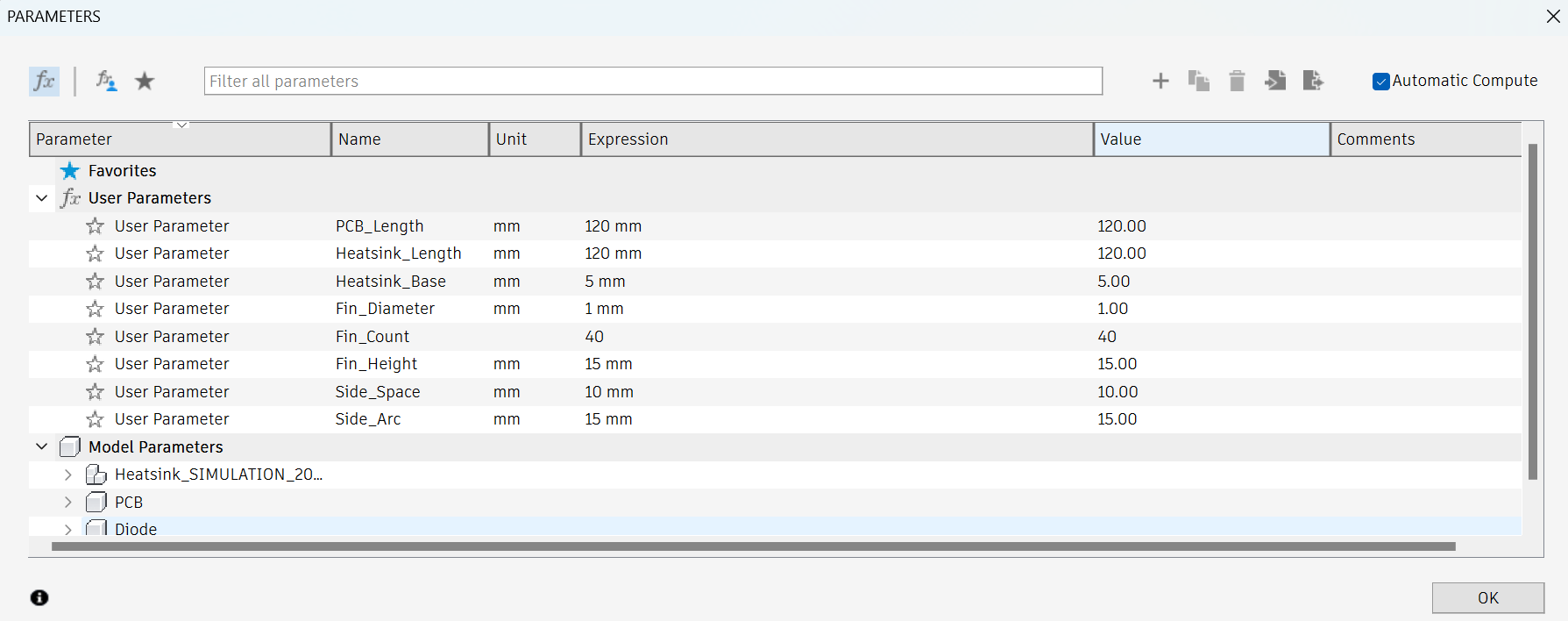 Parametric design of the heatsink
The design was printed on a Prusa i3 MK3S using Prusament PLA. This makes the printing process a bit easier since the PrusaSlicer has already all the settings for this filament. Since the model is just a mock-up, I have used a 0.30 mm DRAFT layer height setting. Additionally, I have increased all the speeds by 20 mm/s for increased print time.
 Finished 3D print on Prusa i3 MK3S